| Update: We found out that the address pins (AB1..AB17) have the wrong pin numbers on our schematic. This means, when we try to read address 0x0002 we do actually access address 0x8000 (AB1 is really AB15). However, that does not explain why we are always reading address 0x0000. Even if we really access address 0x8000 we should always read a different value... |
Update #2: Problem solved! Correcting the address pins the connection between the processor and the controller works as expected when using General Interface #1. We have no idea why G.I.#2 does not work in any way but in any case G.I.#1 is what we wanted to use from the beginning on. Thanks a lot to all the people that were willing to help us! |
We are trying to make the above EPSON LCD controller work with the ETRAX processor. We both tried general interface #1 and general interface #2 - the latter as described in the Thesis by Magnus Kling, Jerker Buud (with the difference that we are using another controller model with more RAM).
The controller has 160kb of embedded RAM and provides a 16 bit bus interface.
Despite lots of tests we still could not achieve a working communication between the two chips. Reading the lower 16 bits of register 0 (product information) returns 0x282C as expected but any other address (like the upper 16 bits of that register) seem to return always the same register. We guess there is a timing problem so that the controller does not recognize the desired address correctly.
Another problem is that when accessing the controller's internal RAM, the WAIT signal gets active (low) and remains there all the time locking up the processor, obviously. This could be because not all necessary EPSON registers have been initialized.
We are using a custom built board with an ETRAX100LX processor, 16 MB RAM, 64 MB Flash, USB and three serial ports onboard (all of these fully tested and working perfectly). The board is designed to use general interface #1 for the Epson controller. We tested two of those boards with same results. One of these boards has been modified afterwards to use general interface #2 (in hope that this solves the problem) and this board is described here.
No (real) operating system is used that could cause problems. We are using our EtraxFlasher product and accessing the address space directly. However, even under Linux with the original framebuffer drivers there is the same problem.
To get a synchronous bus, the EPSON master clock is driven by the 50 MHz of the ETRAX RAM clock and thus the EPSON controller is driven at 50 MHz with 2,5 volts supply voltage (Vdd).
The controller is activated via chip select 0 (SRAM bank 0) because only then "common write enable" is available. The internal cache of the ETRAX is bypassed. The ETRAX processor is configured for maximum waitstates.
We attached a 8-channel logic analyzer to the most important signals. These are 32-bit accesses that the processor translates to two 16-bit accesses, of course.
Source: Designer's Reference
Source: EPSON controller's datasheet
As you can see the WAIT signal is extremely short. We are not shure if this is normal. It could be that accesses to the registers are in fact very fast.
This should not directly affect the processor as it is configured for maximum waitstates and thus waits longer anyway. But, it deserves our attention...
First address 0 is read, then address 2 (both 16 bits). However, it reads 0x282C282C where it should read 0x2Cxx282C.
Strangely the WAIT signal arrives before the RD signal is set (but the timing diagram from the data sheet tells us something else).
Same here...
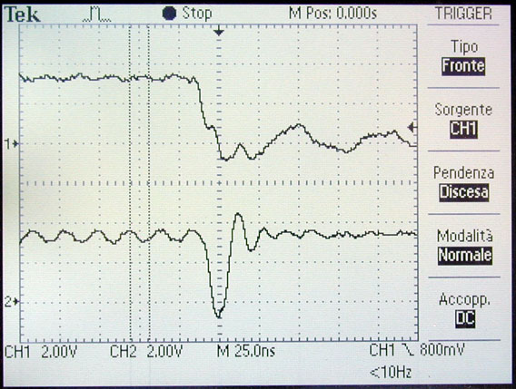
Here you can see the CS (top) and WAIT# (bottom) signals during a read access. Like the digital analysis above the WAIT# signal is very short. Note the WAIT# signal is tied to 3.3V using a 15KOhm pull-up resistor.
We analyzed the original Linux Framebuffer driver for the chip and tried to configure it manually with the same register values (address, value):
 0x88000014  0x00000000
 0x88000064  0x28D70000
 0x88000004  0x00000000
 0x88000008  0x00000003
 0x8800000C  0x00000000
 0x88000010  0x00000004
 0x88000020  0x0000002B
 0x88000024  0x00000027
 0x88000028  0x00000000
 0x8800002C  0x00870156
 0x88000030  0x000000FA
 0x88000034  0x000000EF
 0x88000038  0x00000000
 0x8800003C  0x00800000
 0x88000040  0x00000000
 0x88000044  0x00000028
 0x88000050  0x00000000
 0x88000054  0x00000028
 0x88000058  0x00000000
 0x8800005C  0x00000000
 0x88000060  0x00000000
 0x88000070  0x00000000
 0x88000074  0x00000000
 0x88000080  0x00000000
 0x88000084  0x00000000
 0x88000088  0x00000000
 0x880000FD  0x00000032
 0x88000064  0x28D70001
 0x88000014  0x00000000
It did not help at all, however when reading back those registers "some nibbles" are correct (another indication that it is a timing problem).
Any suggestions? Please contact us! info@indunet.it (in german, italian or english - which one you prefer)
end of document.